Event Programmierug
Most models require only very simple programs. Buttons control the motors. Buttons and motors are defined in setup. The state of the buttons is monitored in loop, and the motors are controlled accordingly.
Every sensor — whether an input, button, or joystick — is polled by the firmware every 25 ms. The firmware detects changes in their signals and can therefore independently control motors, servos, or LEDs.
Experiment #1: A switch controls a motor
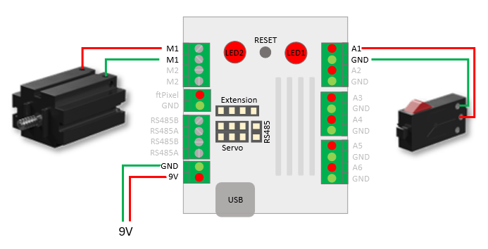
Like any sensor, the switch has three trigger events:
- TriggerUp: This event is triggered when the signal from a digital sensor changes from 0 to 1. For example, when a button or switch is pressed.
- TriggerDown: This event is the opposite of TriggerUp. It is triggered when a button or switch is released.
- ChangeValue: This signal responds to every status change. It is designed to use analog signals—such as those from a joystick—to control the motor speed.
Each trigger can trigger an action. In our example, we want to control the motor speed. To do this, we need two events. When TriggerUp occurs, the motor should turn on; when TriggerDown occurs, it should turn off again.
If necessary, flash the firmware to the controller, connect to a serial console, and start the firmware using setup. From the main menu, select “(r) Remote/Event Configuration”:
***** Remote Configuration *****


(+)  add event
(s)  switch configuration

(x)  Exit

Remote Configuration>
Select “(+) add event” and enter the following values:
Enter sensor's name: A1
Enter trigger event - (0) Trigger down  (1) Trigger up  (2) Change Value [0]: 1

ftSwarm1010.A1.TriggerUp
Enter actor's name: M1

ftSwarm1010.A1.TriggerUp -> ftSwarm1010.M1.setSpeed(
Use - (0) fixed value  (1) sensor's value  (2) actor's value: [0] 0
Enter speed (-100..100) [0]: 100

ftSwarm1010.A1.TriggerUp -> ftSwarm1010.M1.setSpeed( 100
(1) add (2) subtract (3) multiply another value - (0) done [0]: 0
The event is now as follows:
ftSwarm1010.A1.TriggerUp -> ftSwarm1010.M1.setSpeed( 100 )
If button A1 is pressed (TriggerUp), the motor speed is set to 100.
Use “(+) add event” to create a second event:
Enter sensor's name: A1
Enter trigger event - (0) Trigger down  (1) Trigger up  (2) Change Value [0]: 0

ftSwarm1010.A1.TriggerDown
Enter actor's name: M1

ftSwarm1010.A1.TriggerUp -> ftSwarm1010.M1.setSpeed(
Use - (0) fixed value  (1) sensor's value  (2) actor's value [0]: 0
Enter fixed value [0]: 0

ftSwarm1010.A1.TriggerDown -> ftSwarm1010.M1.setSpeed( 0
(1) add (2) subtract (3) multiply another value - (0) done [0]: 0
The two events now look like this:
ftSwarm1010.A1.TriggerUp -> ftSwarm1010.M1.setSpeed( 100 )
ftSwarm1010.A1.TriggerDown -> ftSwarm1010.M1.setSpeed( 0 )
Exit the remote configuration by selecting “(x) exit” and save the change.
Press the switch. The motor starts. Release the switch. The motor stops.
You’ve written a program without a single line of code. The firmware does all the work.
Event programming isn’t limited to buttons and motors. All sensors can trigger events, and (almost) all actuators can be controlled. For example, the color of an ftPixel can be adjusted based on the ambient light level measured by a phototransistor.
Experiment #2: Code
In the first example, we defined the events in the firmware. This can also be combined with a separate program. Triggers handle simple tasks, while the program focuses on complex control tasks. Since this approach can quickly become confusing, it is better to define the triggers in the program:
FtSwarmSwitch *sw;
FtSwarmSMotor  *mot;

void setup( ) {

  // start the swarm
  ftSwarm.begin( );

  // get switch and motor instances
  sw  = new FtSwarmSwitch( "A1" );
  mot = new FtSwarmSMotor( "M1" );

  // set triggers
  sw.onTrigger( FTSWARM_TRIGGERUP,   FTSWARM_ASSIGN, FTSWARM_CONSTANT, FTSWARM_CONSTANT, mot, 100 );
  sw.onTrigger( FTSWARM_TRIGGERDOWN, FTSWARM_ASSIGN, FTSWARM_CONSTANT, FTSWARM_CONSTANT, mot, 0 );

}

void loop( ) {

  // wait some time
  delay(100);

}
Here, too, the firmware does all the work. Defining the triggers is all it takes to activate the motor.
Please delete any existing triggers in the firmware before installing the program.
Experiment #3: A joystick controls the motor speed
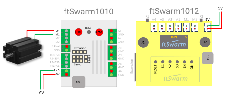
The motor should now be controlled using the left joystick. In the firmware’s main menu, select “(r) Remote/Event Configuration” and create a new event. Be sure to adjust the serial numbers to match your test setup:
Enter sensor's name: ftSwarm1012.JOY1FB
Enter trigger event: change value.
Enter actor's name: ftSwarm1010.M1

ftSwarm1012.JOY1FB.ChangeValue -> ftSwarm1010.M1.setSpeed(
Use - (0) fixed value  (1) sensor's value  (2) actor's value [0]: 1

ftSwarm1012.JOY1FB.ChangeValue -> ftSwarm1010.M1.setSpeed( ftSwarm1010.JOY1FB.getValue()
- **Constant**: Here you can enter a fixed value, such as a motor speed, a servo position, or the color of the LED.
- **Sensor Reading**: Uses the sensor’s current reading. For example, the motor speed can be set using the joystick’s reading (-100..100).
- **Sensor Delta**: Instead of the sensor reading, the change in the sensor reading is used here. This can be used, for example, to implement caterpillar tracks.
- **Actuator Setpoint**: This is, for example, the motor speed.
- **Flashing Effect**: The ftPixel or the lamp is switched to a flashing mode (see above).

You can now process the selected value with a second value:0

ftSwarm1012.JOY1FB.ChangeValue -> ftSwarm1010.M1.setSpeed( ftSwarm1010.JOY1FB.getValue() )
Move the left joystick forward and backward. The motor speed is adjusted according to the joystick’s position. Push the joystick forward to make the motor rotate in one direction. Pull the joystick backward to reverse the direction of rotation.
EExperiment #4: Toggling an ftPixel
We now want to use the S1 button to change the color of an onboard pixel on the ftSwarmRS. You can continue using the setup from Experiment #3. In the firmware, go back to “(r) Remote/Event Configuration” and add the following event:
Enter sensor's name: S1
Enter trigger event - (0) Trigger down  (1) Trigger up  (2) Change Value [0]: 1

ftSwarm1012.S1.TriggerUp
Enter actor's name: ftSwarm1010.LED1

ftSwarm1012.S1.TriggerUp -> ftSwarm1010.LED1.setColor(
Use - (0) fixed value  (1) sensor's value  (2) actor's value [0]: 0
Enter RGB value (0..#FFFFFF) [#000000]: #FF0000

ftSwarm1012.S1.TriggerUp -> ftSwarm1010.LED1.setColor( #FF0000
(1) add (2) subtract (3) multiply another value - (0) done [0]: 0

ftSwarm1012.S1.TriggerUp -> ftSwarm1010.LED1.setColor( #FF0000 )
Create a second trigger on S1 that sets the color to #FF00 when TriggerDown is triggered:
ftSwarm1012.S1.TriggerDown -> ftSwarm1010.LED1.setColor( #00FF00 )
Press the S1 button. The pixel changes color to red. As soon as you release the button, the color changes back to green.
Experiment #5: Blinking
We now want to use button S1 to make an onboard pixel on the ftSwarmRS blink. You can continue using the setup from Experiment #3. In the firmware, switch back to “(r) Remote/Event Configuration”. Delete all events marked with “*” and use “+” to add the following events:
Enter sensor's name: S1
Enter trigger event - (0) trigger down  (1) trigger up  (2) change value [0]: 1

ftSwarm1012.S1.TriggerUp
Enter actor's name: LED1

ftSwarm1012.S1.TriggerUp -> ftSwarm1010.LED1.setColor(
Use - (0) fixed value  (1) sensor's value (2) sensor's delta (3) actor's value (4) blink effect [0]: 4
Enter the duration of one beat (0.25s .. 7.00s in 0.25 steps) [0]: 2
Enter number of signal beats (0..15) [0]: 5
Enter signal duty (0) 25/75 (1) 50/50 (2) 75/25 [0]: 1
Enter number of pause beats (0..15) [0]: 3
Enter signal color (0) Black  (1) Red  (2) Green  (3) Blue  (4) Yellow  (5) Orange  (6) Cyan  (7) Pink  (8) Magenta  (9) White  [Black]: 1
Enter signal pause color (0) Black  (1) Red  (2) Green  (3) Blue  (4) Yellow  (5) Orange  (6) Cyan  (7) Pink  (8) Magenta  (9) White  [Black]: 2
Enter pause color (0) Black  (1) Red  (2) Green  (3) Blue  (4) Yellow  (5) Orange  (6) Cyan  (7) Pink  (8) Magenta  (9) White  [Black]: 0
ftSwarm1012.S1.TriggerUp -> ftSwarm1010.LED1.setColor( Blink( period: 2000 ms, signal beats: 5, duty: 1, pause beats: 3, signal color Red, signal pause color: Green, pause color: Black ) )
Create a second trigger on S2 where you set the color to 0 using TriggerDown:
ftSwarm1012.S1.TriggerDown -> ftSwarm1010.LED1.setColor( #000000 )
Press the S1 button. The pixel changes color 5 times from red to green. After that, the LED is off for 3 cycles.
In addition to LEDs, lamps can also flash. In this case, the lamp’s brightness is adjusted instead of its color.

Calculate actor’s value
After entering the actor’s name, the firmware asks to calculate it’s value:
Use - (0) fixed value (1) sensor's value (2) sensor's delta (3) actor's value (4) blink effect [0]:
- fixed value: Here you can enter a fixed value, such as a motor speed, a servo position, or the color of the LED.
- senso’s value: Uses the sensor’s current reading. For example, the motor speed can be set using the joystick’s reading (-100..100).
- sensor’s delta: Instead of the sensor reading, the change in the sensor reading is used here. This can be used, for example, to implement caterpillar tracks.
- actor’s value: This is, for example, the motor speed.
- blink effect: The ftPixel or the lamp is switched to a flashing mode (see above).
You can now process the selected value with a second value:
(1) add (2) subtract (3) multiply another value - (0) done [0]:

Use - (0) fixed value  (1) sensor's value (2) sensor's delta (3) actor's value [0]:
For example, the motor speed can be adjusted by pressing buttons:
(1) ftSwarm1012.F1.TriggerUp -> ftSwarm1012.M1.setSpeed( ftSwarm1012.M1.getSpeed() + 10 )
(2) ftSwarm1012.F2.TriggerUp -> ftSwarm1012.M1.setSpeed( ftSwarm1012.M1.getSpeed() - 10 )
A catapillar drive can be implemented using 4 events:
( 1) ftSwarm1010.JOY1FB.ChangeValue -> ftSwarm1010.M1.setSpeed( ftSwarm1010.M1.getSpeed() + ftSwarm1010.JOY1FB.getDelta() )
( 2) ftSwarm1010.JOY2LR.ChangeValue -> ftSwarm1010.M1.setSpeed( ftSwarm1010.M1.getSpeed() + ftSwarm1010.JOY2LR.getDelta() )
( 3) ftSwarm1010.JOY1FB.ChangeValue -> ftSwarm1010.M2.setSpeed( ftSwarm1010.M2.getSpeed() - ftSwarm1010.JOY1FB.getDelta() )
( 4) ftSwarm1010.JOY2LR.ChangeValue -> ftSwarm1010.M2.setSpeed( ftSwarm1010.M2.getSpeed() - ftSwarm1010.JOY2LR.getDelta() )
Please note that the flashing effect cannot be processed with other values.