A first Swarm
In the “The first program” you have written a simple program and started it on a controller. But how does an application work in a swarm? In this example, the same task - controlling a motor using a pushbutton - is implemented with two controllers.
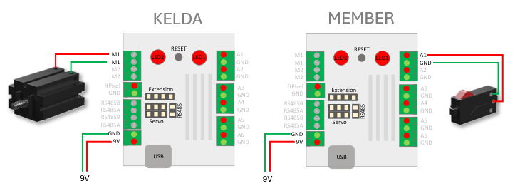
Build a swarm
The second controller must now be added to the swarm. To do this, you must flash the default firmware onto the controller from the first example.
Now connect to the controller using a serial console and enter the firmware by typing setup.
***** Main Menu *****

(w)  Wifi & Local Settings
(s)  Swarm Configuration
(i)  IO Configuration
(r)  Remote/Event Configuration
(f)  Factory Reset

(x)  Exit

setup>
Choose “(s) Swarm Configuration”.
***** Swarm Configuration *****

     Swarm Name: ftSwarm1010
     Kelda: ftSwarm1010
(w)  Communication WIFI: on
     Pin: 1010

     Name         Status   NW-Age    Alias
( 1) ftSwarm1010  ONLINE   [000022]


(n)  create new swarm
(+)  add a controller to my swarm
(a)  set alias name

(x)  Exit

Swarm Configuration>
Use ”(+) add a controller to my swarm” to add the second controller to your swarm.
     Name         Status   NW-Age    Alias
( 1) ftSwarm1010  ONLINE   [000022]
( 2) ftSwarm1011  ONLINE   [000019]
The controllers communicate via wifi. Therefore, your second controller must also use the same wifi network. There are two ways to do this: You can configure its wifi settings via the serial console, or Kelda can transfer these settings to the new Swarm member. If the Kelda cannot find the new swarm member on the wifi network, it will search for the second controller’s default wifi network and transfer its own wifi configuration to the new swarm member.
Both controllers are now displayed on the Kelda web UI. The second controller displays only its own inputs and outputs.
A distributed application
Once both controllers have formed a swarm, you can run the following example on the Kelda. Please enter the serial number of your second controller at #define REMOTE 2:
#include <ftSwarm.h>

// serial number of the second controller - change it to your 2nd device serial number
#define REMOTE 2

FtSwarmSwitch *sw;
FtSwarmSMotor *mot;

void setup( ) {

  // start the swarm
  FtSwarmSerialNumber_t local = ftSwarm.begin( );

  // get switch and motor instances
  sw  = new FtSwarmSwitch( REMOTE, FTSWARM_A1 );
  mot = new FtSwarmSMotor( local, FTSWARM_M1 );

}

void loop( ) {

  // check if switch is pressed or released
  if ( sw->isPressed() )
    mot->setSpeed(100);
  else
    mot->setSpeed(0);

  // wait some time
  delay(100);

}
Basically, the application is the same as Your First Application. There are only two changes:
- #define REMOTE 2 sets the serial number of your 2nd device. Please change the serial number to your 2nd device serial number.
- FtSwarmSwitch( REMOTE, FTSWARM_A1 ); now uses the remote device serial number instead of the local serial number.
What happens, if the 2nd controller isn’t online?
Start the serial monitor and unplug the 9V power supply from the second device. Restart the first one. With FtSwarmSwitch( REMOTE, FTSWARM_A1 ); you will get the debug output Waiting on device. Both RGB leds of this controller will be blue. The firmware waits for the switch joining the swarm. Add the 9V power supply again. Once the second device is started, your application will continue.